1. Overview
The horizontal slurry pump is a cantilever, centrifugal slurry pump suitable for handling abrasive or corrosive slurries. It is widely used in metallurgy, mining, petroleum, chemical, coal, electric power, transportation, river dredging, building materials, and municipal engineering sectors. According to their structural features and scope of application, the pumps are classified into the following types:
1. AH, AHP, HP, M, H and HH pumps, also known as heavy-duty slurry pumps. Since these pumps are provided with thicker wear parts and heavy-duty frames, they are suitable for handling highly abrasive, high-concentration slurries or low-concentration, high-head slurries; within the maximum allowable working pressure of the pump, they can be operated in multi-stage series. Among them, the HH pump is suitable for handling low-concentration, high-head slurries or high-concentration, low-abrasiveness, high-head slurries. The above types of pumps can also be used for slurries with a certain degree of abrasiveness.
2. L pumps, also known as light-duty slurry pumps. Compared with heavy-duty slurry pumps, these pumps run at higher speeds and are smaller in size and lighter in weight. They are suitable for handling fine-particle, low-concentration slurries or corrosive slurries. The solids concentration by weight of the conveyed slurry generally does not exceed 30%; they can also be used for high-concentration, low-abrasiveness slurries.
3. D dredge pumps and G gravel pumps: these pumps have large flow passages and are suitable for handling gravel, mud and slurries with large solid particles.
4. AHR, LR and MR pumps: the wetted parts of these pumps are made of rubber. Their casings, casing covers and drive parts are interchangeable with those of AH, L and M pumps. They are suitable for handling fine-particle and corrosive slurries.
Model designation:
10 / 8 ST – AH
| Designation | Meaning |
|---|---|
| AH | AH type pump (heavy-duty slurry pump) |
| ST | ST type frame |
| 10 | Suction diameter 10 inches |
| 8 | Discharge diameter 8 inches |
2. Structure Description
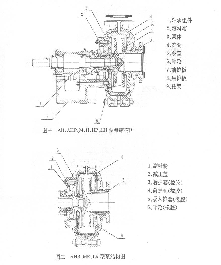
See Fig. 1 for structural drawings of AH, AHP, HP, M, H and HH pumps
See Fig. 2 for structural drawings of AHR, MR and LR pumps
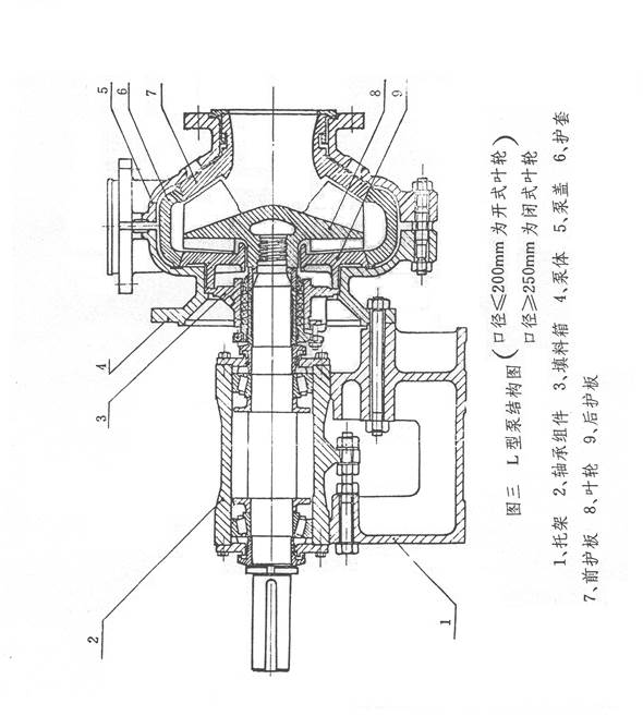
See Fig. 3 for the structural drawing of the L pump
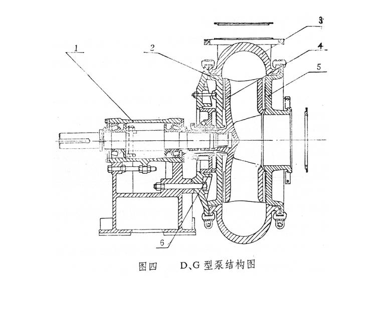
See Fig. 4 for structural drawings of D and G pumps
Except for the pump head (including casing, casing cover, impeller, etc.), which differs in structure, all the above types of horizontal slurry pumps are similar in the remaining parts and adopt the same series of drive parts. The structural features are described below by pump head, shaft seal and drive parts.
1. Pump head
L, M, AH, AHP, HP, H and HH pumps are of double-casing construction, i.e. the casing and casing cover are fitted with replaceable wear-resistant metal liners (including impeller, volute liner, liner plates, etc.). The casing and casing cover are made of grey cast iron or nodular cast iron according to the working pressure, split vertically and joined by bolts. The casing has a spigot that is bolted to the frame. The pump discharge outlet can be rotated and installed at eight different angles. The front and back shrouds of the impeller carry back vanes to reduce leakage and extend the service life of the pump.
AHR, LR and MR pumps are also of double-casing construction; the casing and casing cover are fitted with replaceable corrosion-resistant rubber liners (including impeller, front liner, rear liner, etc.). The casing and casing cover are interchangeable with those of AH, L and M pumps, and the drive parts and mounting arrangement are the same as those of AH, L and M pumps.
D and G pumps are of single-casing construction (i.e. without liners). The casing, casing cover and impeller are all made of wear-resistant metal. The casing and casing cover are joined by a special clamping structure; the discharge outlet can be rotated to any direction, and installation and disassembly are easy.
The suction inlets of all pump types are horizontal in direction, and viewed from the drive end the pump rotates clockwise.
2. Shaft seal
There are two types of shaft seal: the expeller shaft seal and the packing shaft seal.
(1) Expeller shaft seal: for single-stage pumps, or for the first-stage pump of a multi-stage series, where the positive pressure at the pump inlet does not exceed 10% of the pump discharge pressure, the expeller shaft seal may be used. The expeller shaft seal has the advantages of requiring no seal water, not diluting the slurry, and providing good sealing performance.
(2) Packing shaft seal: the packing shaft seal is simple in structure and easy to maintain, but seal water must be used. The packing shaft seal can be adopted for operating conditions unsuitable for the expeller shaft seal.
3. Drive parts
All horizontal slurry pumps adopt the same series of drive parts, including the frame and the bearing assembly. The pump shaft is of large diameter and high rigidity with a short cantilever, and will not bend or vibrate under severe operating conditions. Depending on the power transmitted, heavy-duty single-row or double-row tapered roller bearings or cylindrical roller bearings are selected; they can withstand the maximum axial and radial loads of the pump. The bearings are grease-lubricated. Both ends of the bearing housing are fitted with sealed end covers, labyrinth sleeves and labyrinth rings, which effectively prevent slurry and other contaminants from entering the bearings, ensuring safe operation and a long service life of the bearings.
3. Assembly Precautions
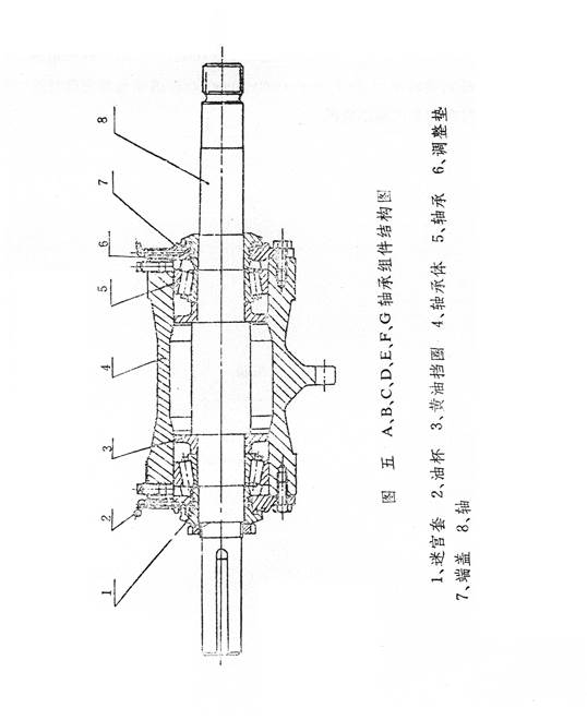
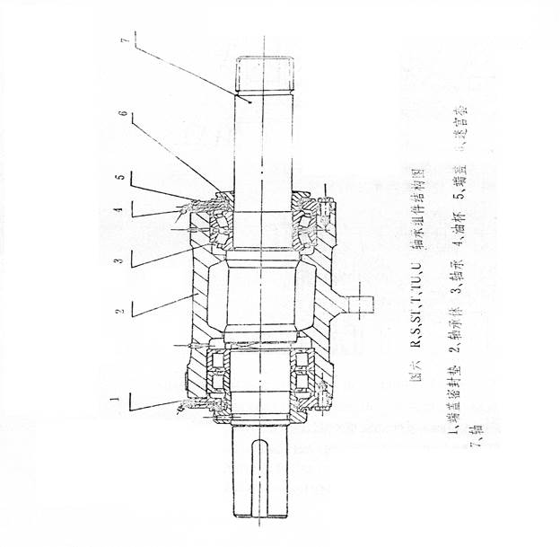
1. Bearing assembly assembly (see bearing assembly drawings Fig. 5 and Fig. 6)
When assembling, preheat the bearing inner rings; the temperature must not exceed 120°C. The bearing inner rings must be pressed tightly against the shaft shoulder or the grease retaining ring. For double-row tapered roller bearings, the inner rings, outer rings and locating sleeves are supplied as matched sets and must not be interchanged with the corresponding parts of similar bearings.
For A, B, C, D, E, F and G bearing assemblies, which use single-row tapered roller bearings, the axial gap is set at assembly by adjusting the shims at the bearing end covers. The axial gap values shall conform to the table below:
| Frame type | A | B | C | D | E | F, G |
|---|---|---|---|---|---|---|
| Axial gap mm | 0.05-0.15 | 0.1-0.2 | 0.15-0.25 | 0.18-0.28 | 0.4-0.6 | 0.5-0.6 |
For R, S, ST, T, TU and U bearing assemblies, the pump end uses double-row tapered roller bearings; since the axial clearance is already ensured by the bearing itself, no adjustment of the axial clearance is required.
When assembling the bearings, take care to add an appropriate amount of bearing grease. The seals at the bearing end covers use labyrinth rings and labyrinth sleeves; when installing the labyrinth rings, make sure the notches are arranged diametrically opposite each other.
Lithium-based grease No. 2 or No. 3 is recommended for the bearings. The amount of grease added at assembly may be determined with reference to the table below, unit: g
| Frame type | B | C | D | E | F | G | R, RS | S, ST | T, TU | |
|---|---|---|---|---|---|---|---|---|---|---|
| Grease quantity | Drive-end bearing | 30 | 50 | 100 | 200 | 500 | 1150 | 200 | 500 | 1150 |
| Pump-end bearing | 30 | 50 | 100 | 200 | 500 | 1150 | 400 | 1000 | 2300 |
2. Assembly of the packing shaft seal assembly
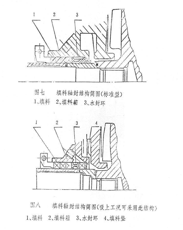
The packing shaft seal assembly comprises the stuffing box, shaft sleeve, locating sleeve, seal ring, packing, packing washer, lantern ring, gland and other parts. The lantern ring comes in two designs; installation drawings are shown in Fig. 7 and Fig. 8. Fig. 7 shows the standard installation arrangement. When the pump operates on suction lift, the installation arrangement in Fig. 8 may be selected. During installation, make sure the seal ring between the shaft sleeve and the locating sleeve is fitted in the correct position.
Packing selection: when the working pressure of the pump is below 1MPa(10kgf/cm2), packing of asbestos fiber impregnated with mica is generally used; when the pressure is above 1MPa(10kgf/cm2) or the pump handles corrosive slurries, packing of asbestos fiber impregnated with polytetrafluoroethylene is used.
3. Installation of the expeller shaft seal assembly (see Fig. 9 and Fig. 10)
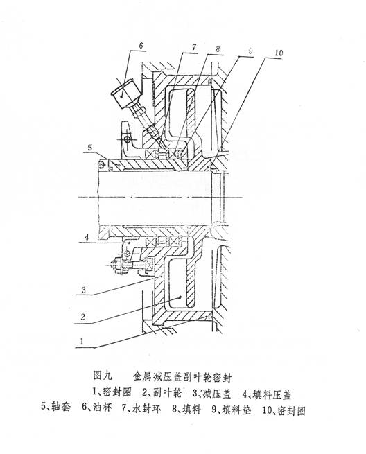
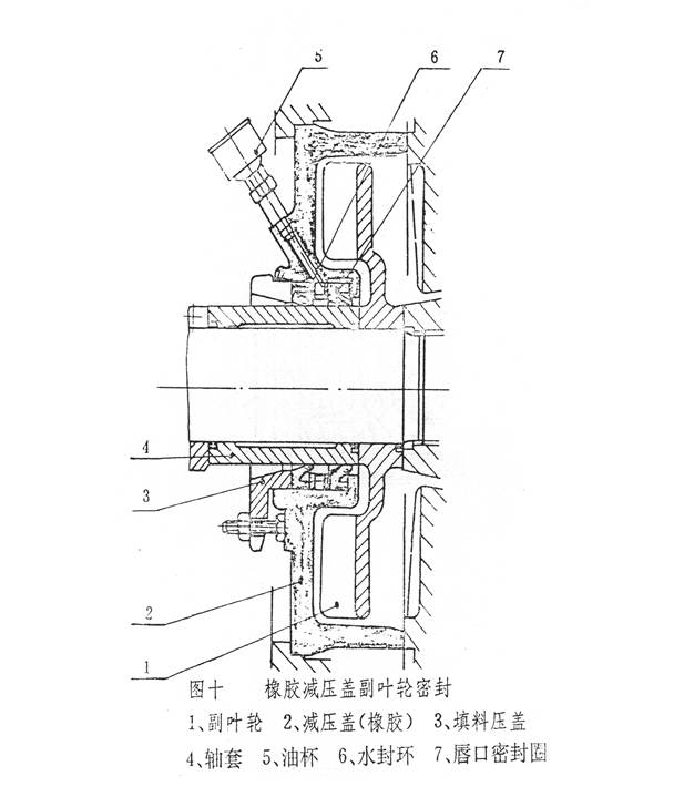
The expeller shaft seal assembly comprises the expeller, expeller cover, shaft sleeve, locating sleeve and other parts. With a rubber expeller cover, a lip seal ring and a lip seal gland are used; with a metal expeller cover, packing, packing washer, lantern ring and gland are used. Users may make a selection according to the different service conditions. When assembling, take care that each seal ring is installed in the correct position.
4. Assembly of the pump head
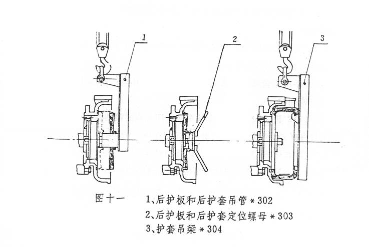
Fit the seal ring into the casing, then install the frame plate liner using the frame plate liner locating nut, install the impeller, then fit the volute liner, and press the volute liner onto the casing with bolts and retaining clamp plates; finally install the throat bush and the casing cover. For rubber-lined pumps, the front liner should first be fitted into the casing cover, the bolts tightened, and then the casing cover joined to the casing. When fitting rubber parts, soap water or rubber lubricant fluid may be applied to the mating surfaces to facilitate assembly. During assembly, make sure all sealing gaskets are placed in the correct positions and compressed. To ensure the correct relative positions of the parts and to facilitate assembly, the following assembly tools may be selected: frame plate liner and rear liner lifting tube *302, frame plate liner and rear liner locating nut *303, and volute liner lifting beam *304; their use is shown in the schematic diagram Fig. 11.
5. Removal ring
Pumps with the high-power R, S, ST, T, TU and U bearing assemblies are fitted with a removal ring. When disassembling, first remove the three hexagon socket bolts on it and screw them into the other three threaded holes in the removal ring to jack the three ring segments of the removal ring off the shaft; only then can the impeller be loosened.
4. Operation
1. Start-up:
Before starting, check the whole unit according to the following steps.
(1) The pump must be mounted on a solid foundation to carry the entire weight of the pump and eliminate vibration; tighten all foundation bolts.
(2) The piping and valves must be supported independently. There is a sealing gasket at the pump flange; when tightening the connecting bolts, note that on some pumps the metal liner protrudes above the flange, in which case the bolts must not be overtightened, so as to avoid damaging the sealing gasket.
(3) Turn the shaft by hand in the direction of pump rotation; the shaft must be able to drive the impeller to rotate without rubbing; otherwise the impeller clearance must be adjusted.
(4) Check the motor rotation direction and make sure the pump rotates in the direction of the arrow marked on the casing. Note that reverse rotation of the pump is not permitted, otherwise the impeller thread will disengage, resulting in damage to the pump.
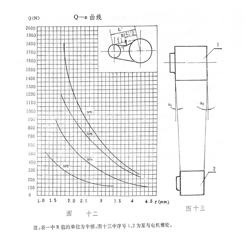
(5) With direct-coupled drive, the pump shaft and the motor shaft must be precisely aligned; with belt drive, the pump shaft and the motor shaft must be parallel, and the groove pulley positions must be adjusted so that they are square with the groove belt, so as to avoid severe vibration and wear. When SPA and SPB groove pulleys are used in matched sets, adjust the pulleys to meet the requirement α1=α2 shown in Fig. 13.
(6) A removable short pipe section should be fitted in the pump suction pipe; its length should be sufficient to allow the casing cover to be removed and the wear parts replaced, for ease of pump maintenance. See the outline dimension drawing of each pump for the length.
(7) Shaft seal check: for pumps with an expeller shaft seal, owing to the different designs of the stationary seal, when a grease cup is fitted on the expeller cover, grease must be added through the grease cup; calcium-sodium based grease is recommended.
Pumps with a packing seal should have the seal water turned on before start-up, and the seal water flow and pressure checked for suitability. Adjust the gland tightening screws to regulate the tightness of the packing and adjust the seal water; it is best if the leakage from the gland seeps out drop by drop. If the packing is too tight, the shaft sleeve heats up easily and power is also wasted; if the packing is too loose, the liquid leakage will be too large. The seal water pressure is generally 3.5×10⁻² MPa(0.35kgf/cm²) above the discharge pressure. The recommended seal water flow is generally given in the table below:
| Frame type | A | B | C | D | E, F | G | R, RS | S, ST | T, TU | U |
|---|---|---|---|---|---|---|---|---|---|---|
| Seal water flow l/s | 0.15 | 0.25 | 0.35 | 0.55 | 0.70 | 1.2 | 0.70 | 1.2 | 1.6 | 2.1 |
2. Operation
(1) During operation, regularly check the pressure and flow of the seal water and adjust the gland or replace the packing in good time, so that a small amount of clean water always passes along the shaft.
(2) Regularly check the operation of the bearing assembly. If the bearings heat up when operation begins, the pump may be stopped and restarted after the bearings have cooled. If the bearings still overheat severely and the temperature keeps rising, the bearing assembly must be dismantled and inspected to find the cause. Bearing overheating is generally caused by excessive lubricating oil or contaminants in the oil; the quantity of bearing grease must be appropriate and the grease clean, and grease must be added regularly.
(3) The performance of the pump changes as the clearance between the impeller and the liner plates increases, and the efficiency drops; therefore the impeller should be adjusted forward in good time to maintain a certain clearance, so that the pump keeps operating at high efficiency. When the pump is worn to the point where it can no longer meet the requirements of the system, the wear parts should be replaced.
3. Stopping the pump:
Before stopping the pump, where possible pump clean water for a while to flush the slurry that has passed through the pump, then close in sequence the pump, the gate valve, and the packing seal water.
4. Adjustment of the V-belt tension
The adjustment method recommended by our factory is introduced below for reference.
(1). First calculate the tension Q, (in newtons)
(2). Based on the tension and the V-belt section, look up the value of e on the curve
(3). Calculate f from the formula
(4). Look up the value of R corresponding to the V-belt section in Table 1; as shown by the method in Fig. 12, adjust the center distance between the two pulleys to achieve the required tension Q. Generally, when a force of R newtons is applied, if the total deflection of the free span does not exceed f, the required tension Q has been achieved.
Where:
- Q — minimum static tension of the free span per V-belt, in newtons
- f — total deflection of the V-belt free span, in mm
- C₁ — angle coefficient, approximately 0.9
- C₂ — service factor, approximately 1.4
- L′ — center distance between the groove pulleys
- P — rated motor power, KW
- Z — number of V-belts
- V — belt speed, meters per second
- M — centrifugal coefficient (see Table 1)
- e — deflection per 100mm of free span length, see Fig. 12
Table 1
| Type | SPA | SPB | SPC | SPZ |
|---|---|---|---|---|
| R | 60 | 90 | 120 | 30 |
| m | 0.12 | 0.20 | 0.38 | 0.08 |
When the V-belts are finally adjusted, the tension should be such that the tension is at its minimum when the load is at its maximum. When V-belts are used as a set, the circumference of each V-belt should be essentially identical, to ensure that each V-belt carries an equal load during operation.
After the V-belts have been adjusted, check again whether the impeller rotates normally. Where possible, the pump should be started with clean water before pumping slurry: open the suction pipe valve, start the motor, check the inlet and outlet pressures and the flow, and check the leakage at the packing. If the packing heats up, first loosen the gland bolts to increase the leakage, and after the packing has run in against the shaft, readjust the leakage to the specified value.
5. Maintenance
To keep the pump operating safely, daily maintenance must be attended to. Maintenance should observe the following aspects:
1. Shaft seal maintenance:
For pumps with a packing shaft seal, regularly check the seal water pressure and flow; always keep a small amount of clean water flowing along the shaft; adjust the gland regularly, inspect the packing and replace it periodically. The seal water pressure and seal water flow shall meet the requirements given above (shaft seal check).
For expeller shaft seal pumps fitted with a grease cup, oil should be injected regularly through the grease cup to lubricate the internal packing or lip seal ring.
2. Impeller adjustment:
To ensure that the pump operates at high efficiency, the clearance between the impeller and the throat bush must be adjusted in good time. For metal-lined pumps the clearance between the impeller and the throat bush should be between 0.5-1mm; for rubber-lined pumps the clearance between the impeller and the front and rear liners must be equal. When adjusting the impeller clearance, first stop the pump, loosen the bolts clamping the bearing assembly, and tighten the nuts on the adjusting bolts to move the bearing assembly forward while turning the shaft by hand in the direction of pump rotation, until the impeller rubs against the throat bush; for metal-lined pumps, then loosen the nut just tightened by half a turn. Then tighten the front nut on the adjusting bolt to move the bearing assembly back; at this point the clearance between the impeller and the throat bush is between 0.5-1mm. For rubber-lined pumps, by tightening the nuts on the adjusting bolts, first move the bearing assembly forward so that the impeller contacts the front liner, then move the bearing assembly back so that the impeller contacts the rear liner, and measure the total travel distance of the bearing assembly; this distance is generally taken as the clearance between the impeller and the front and rear liners. Then use the adjusting bolts to regulate the position of the bearing assembly to ensure the correct clearance values between the impeller and the front and rear liners. After adjustment, before starting again, it is necessary to recheck whether the impeller rotates normally and whether the bearing assembly clamping bolts and adjusting bolts are tightened, and only then start the pump.
3. Bearing lubrication:
If the bearing assembly is correctly assembled, lubricated with the proper amount of oil and maintained in good time, it will have a long service life. Maintenance personnel should overhaul the bearing assembly at regular intervals and check the condition of the bearings and the grease; the overhaul interval is generally not more than 12 months. During operation, grease must be added at regular intervals; the interval and the amount of grease added are related to many factors such as the pump speed, bearing size, continuous running time, number of pump starts and stops, ambient environment and running temperature. Moreover, excessive grease causes bearing overheating, so experience must be gradually accumulated and grease added reasonably and in good time. Under normal circumstances the table below may be used as a reference.
4. Standby pumps should have the shaft turned 1/4 of a revolution each week, so that the bearings carry the static load and external vibration evenly.
Grease quantity and lubrication interval table (hours)
| Frame type | Grease quantity per bearing (g) | Bearing speed r/min | |||||||||
|---|---|---|---|---|---|---|---|---|---|---|---|
| 200 | 300 | 400 | 600 | 800 | 1000 | 1200 | 1800 | 2000 | |||
| B | 12 | 3000 | 2400 | 1800 | 1500 | 1000 | |||||
| C | 18 | 3600 | 2400 | 1800 | 1600 | 1200 | 900 | ||||
| D | 28 | 2500 | 2000 | 1500 | 1200 | 800 | 500 | ||||
| E | 44 | 5000 | 3600 | 2200 | 1600 | 1100 | 800 | 500 | |||
| F | 71 | 7000 | 4200 | 2000 | 1800 | 1200 | 700 | 400 | |||
| Pump end | R, RS (102) | 3000 | 2000 | 1400 | 1000 | 600 | 400 | 100 | |||
| S, ST (132) | 3800 | 2800 | 1500 | 900 | 500 | 300 | |||||
| T, TU (304) | 4800 | 3000 | 1800 | 900 | 400 | ||||||
| U (621) | 4000 | 2400 | 1500 | 500 | |||||||
| R, RS (61) | 8000 | 4800 | 3500 | 2800 | 2200 | 1500 | 900 | ||||
| Drive end | S, ST (74) | 8000 | 6000 | 3600 | 2400 | 1600 | 1200 | ||||
| T, TU (133) | 8000 | 7000 | 4500 | 2500 | 1500 | ||||||
| U (192) | 7000 | 6000 | 4000 | 2000 | |||||||
The grease specified above is for lubricating the bearings. For the various bearing assemblies, on the bearing assembly the inner grease plug is for adding bearing grease, and the inner grease cup is used for cleaning the labyrinth seal. In addition to adding grease periodically through the grease plug, clean grease should also be added frequently through the grease cup to keep the labyrinth seal clean.
6. Possible Faults and Solutions
| Fault | Cause | Solution |
|---|---|---|
| Pump fails to draw water | Air leakage in the suction line or at the packing; wrong rotation direction or damaged impeller; suction pipe blocked | Seal the leaking parts; check the rotation direction and fit a new impeller; clear the blockage |
| Excessive shaft power | Gland too tight, packing heating up; rubbing inside the pump; bearing damage; drive belt too tight; pump flow too high; speed too high or specific gravity too high; motor shaft and pump shaft misaligned or not parallel | Loosen the gland bolts; eliminate the rubbing; replace the bearings; adjust the belt; adjust the operating conditions of the pump; adjust the speed; align the motor shaft and the pump shaft |
| Bearing overheating | Too much or too little bearing grease; contaminants in the grease; bearing damage | Add grease in the proper amount; renew the grease; fit new bearings |
| Short bearing life | Motor shaft and pump shaft misaligned or not parallel, shaft bent; rubbing inside the pump or impeller out of balance; foreign matter entered the bearing or improper grease quantity; incorrect bearing assembly | Align the motor shaft and the pump shaft; replace the shaft and clean the shaft; eliminate the rubbing and fit a new impeller; replace the bearings or reassemble the bearings |
| Severe leakage at the packing | Packing severely worn; shaft sleeve severely worn; seal water not clean | Renew the packing; replace the shaft sleeve; supply clean seal water |
| Pump vibrates with loud noise | Bearing damage; impeller out of balance; air ingress or blockage in the suction pipe; uneven flow, pump running empty | Fit new bearings; fit a new impeller; eliminate the air ingress and clear the blockage; improve the pump feed conditions |