1. Overview
The ZGB(P) series slurry pumps are a new type of product independently developed and designed by our plant for ash and slag removal duties, on the basis of many years of slurry pump design and manufacturing experience and by extensively drawing on advanced domestic and international technologies and research achievements. This series of products offers remarkable advantages such as rational structure, high efficiency, long service life, high reliability, easy maintenance and low operating costs. It is widely used in the electric power, metallurgy, mining, coal, building materials and chemical industries to handle abrasive or corrosive slurries, and is particularly suitable for power plant ash handling.
Pump model designation:
Example: 100ZGB(P)
| 100 | Z | G | B | (P) |
|---|---|---|---|---|
| Discharge outlet diameter (mm) | Slurry pump | High head | Series code | Multi-stage series, stages 3-4 (stages 1 and 2 are unmarked) |
2. Structure Description
The ZGB(P) series slurry pumps are similar in structure: they are horizontal, single-stage, single-suction, cantilever, double casing centrifugal pumps. Their structural features are described separately below for the pump head section, the shaft seal section and the drive section.
2.1 Pump head section
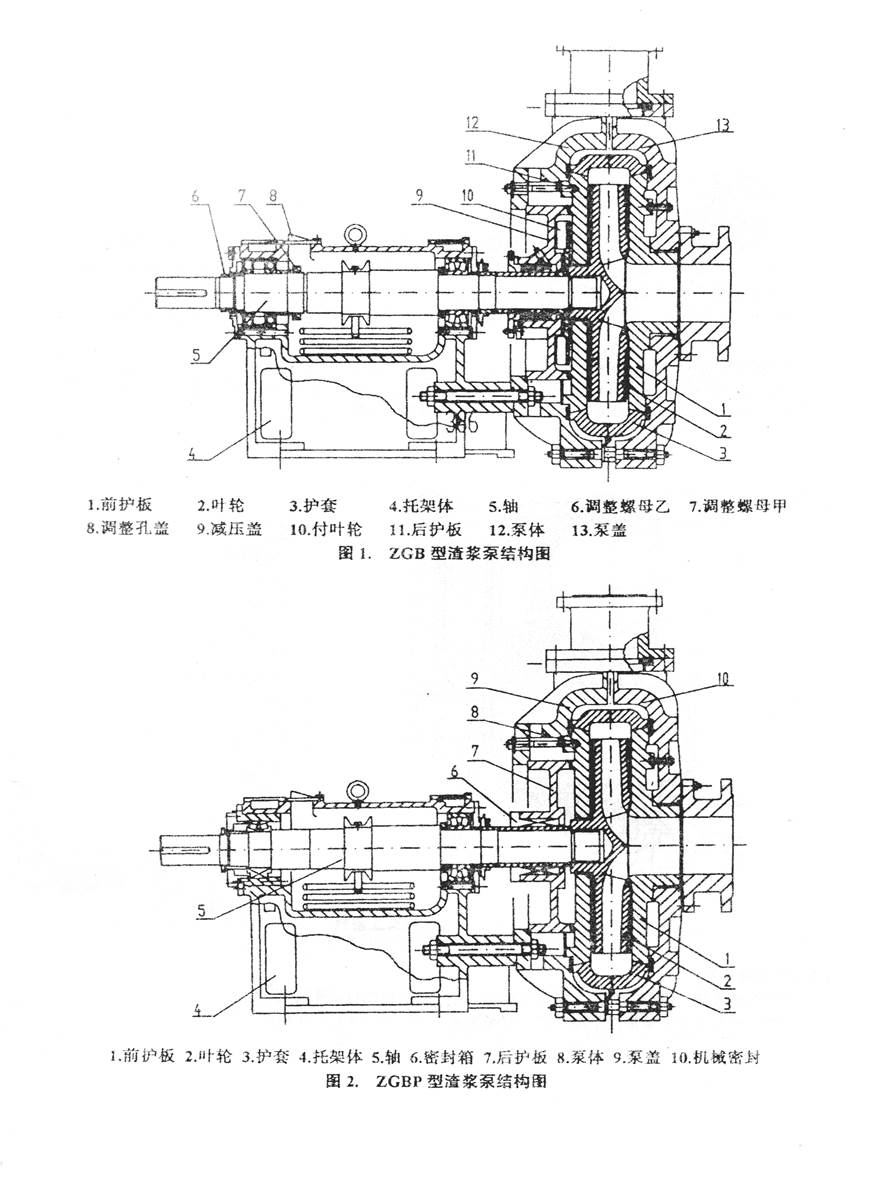
The ZGB(P) series slurry pumps are of double casing construction, i.e. the casing and casing cover are fitted with replaceable wear-resistant metal liners (including the volute liner, liner plates, etc.), as shown in Fig. 1 and Fig. 2. The casing and casing cover are made of grey cast iron or ductile iron depending on the working pressure. All pumps in this series are of vertically split design, and the discharge outlet can be rotated and installed at eight positions at 45° intervals. Expellers are provided at the front and rear shrouds of the impeller to reduce leakage and extend the service life of the pump.
The inlets of this series are all horizontal, and the pump rotates clockwise when viewed from the drive end. During start-up and operation, reverse rotation of the motor is strictly prohibited; otherwise the impeller may come off the shaft and cause an accident.
2.2 Shaft seal section
Two types of shaft seal are available:
(1) Expeller-plus-packing combination seal: this seal type is a high-performance seal developed by our plant using reliability-based design, which reduces shaft seal leakage to a minimum. It can also operate normally, with no leakage at all, in certain special duties (single stage) where dilution of the conveyed product is not permitted and no shaft seal water can be supplied. The expeller, expeller cover and shaft sleeve are all made of wear-resistant materials, requiring little maintenance and offering a long service life, which greatly increases the mean time between failures (MTBF) of the complete pump.
(2) Mechanical seal: this seal type is particularly suitable for sealing multi-stage series slurry pumps and is completely leak-free.
For slurry pumps operating in series at the second stage and above, a mechanical seal with high-pressure shaft seal water is recommended; for single-stage pumps, the expeller-plus-packing combination seal is used.
2.3 Shaft seal water pressure
For single-stage pumps (or the first stage of a series) with the packing-plus-expeller combination seal, the shaft seal water pressure should generally be no less than 0.2 MPa.
For multi-stage series operation with the packing-plus-expeller combination seal, the shaft seal water pressure for the second stage and above is generally:
Minimum shaft seal water pressure for stage n = ∑(i=1→n-1) Hi + 0.7Hn, where n≥2
For pumps with mechanical seals, the shaft seal water pressure of each stage is generally required to be 0.1 MPa higher than the pump discharge pressure.
The shaft seal water flow rates for the various seal types are given in Table 1.
Table 1: Shaft seal water parameters
| Pump model | Frame | Shaft seal water flow (L/s) | Shaft seal water connection | Frame cooling water connection | Frame cooling water pressure |
|---|---|---|---|---|---|
| 65ZGB | 320 | 0.5 | 1/4" | 1/2", 3/8" | 0.05-0.2 MPa |
| 80ZGB | 406 | 0.7 | 1/2" | 3/4", 1/2" | 0.05-0.2 MPa |
| 100ZGB | 406 | 0.7 | 1/2" | 3/4", 1/2" | 0.05-0.2 MPa |
| 80ZGB | 406A | 0.7 | 1/2" | 3/4", 1/2" | 0.05-0.2 MPa |
| 100ZGB | 406A | 0.7 | 1/2" | 3/4", 1/2" | 0.05-0.2 MPa |
| 150ZGB | 565 | 1.2 | 1/2" | 3/4", 3/4" | 0.05-0.2 MPa |
| 200ZGB | 565 | 1.2 | 1/2" | 3/4", 3/4" | 0.05-0.2 MPa |
| 150ZGB | 565A | 1.2 | 1/2" | 3/4", 3/4" | 0.05-0.2 MPa |
| 200ZGB | 565A | 1.2 | 1/2" | 3/4", 3/4" | 0.05-0.2 MPa |
| 250ZGB | 743 | — | 1" | — | 0.05-0.2 MPa |
| 300ZGB | 743 | — | 1" | — | 0.05-0.2 MPa |
| 250ZGB | 743A | — | 1" | — | 0.05-0.2 MPa |
2.4 Drive section
All ZGB(P) series slurry pumps use the same family of drive sections — the frame. The pump shaft is of large diameter, high rigidity and short cantilever length, so that it will not bend or vibrate under severe duty conditions. The frames of this series all use thin-oil lubrication; the bearings are mounted directly in the horizontally split frame body, which makes disassembly, inspection and adjustment convenient. A water cooling system is also provided, which improves the working conditions of the bearings, keeps them running at a lower temperature and greatly extends bearing life.
3. Assembly
3.1 Bearing assembly installation
During assembly, preheat the bearings; the oil temperature must not exceed 120°C.
The bearing clearance has been adjusted before the pump leaves the factory and is generally between 0.2 and 0.5 mm. When dismantling, overhauling or replacing the bearings, please note: to ensure the bearing clearance, add paper gaskets between the bearing cover and the frame body (or the bearing housing) to adjust the bearing clearance so that it remains within 0.2-0.5 mm.
The frame body is fitted with an oil level gauge; the oil level should always be kept at the middle of the gauge. The lubricating oil is generally No. 20, No. 30 or No. 40 machine oil.
3.2 Assembly of the expeller-plus-packing combination seal
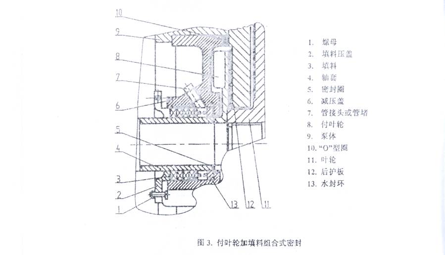
The expeller-plus-packing combination seal comprises the expeller, expeller cover, shaft sleeve, packing, lantern ring and gland, etc. During assembly, take care that all "O"-rings are fitted in the correct positions. The assembly drawing of this unit is shown in Fig. 3.
3.3 Mechanical seal installation
Cleanliness is of utmost importance when installing a mechanical seal. Before installation, in addition to cleaning all mechanical seal parts, the seal chamber end face and bore wall and the surfaces of the shaft and shaft sleeve must also be wiped clean and checked for burrs, damage, etc., with any defects rectified promptly. In particular, the sealing faces of the rotating and stationary rings of the mechanical seal must be carefully wiped clean with degreasing cotton or high-grade tissue paper. Make sure they are free of scratches or scuffing, then apply a coat of clean machine oil to them; the sealing faces must be perfectly clean before and after they are mated in installation, otherwise the sealing performance will be affected.
Mechanical seal parts are precision components; forcing them with hammering during assembly is strictly prohibited. The sealing faces of the rotating and stationary rings in particular are of high precision and must be given extra protection; knocks and scratches are not permitted.
To facilitate assembly, a coat of clean machine oil or grease may be applied to the rubber "O"-rings and the related parts.
The specific assembly sequence is as follows:
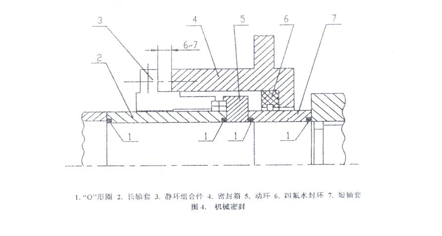
(1) Fit the "O"-ring and the long shaft sleeve onto the pump shaft (if a retaining washer is provided, first butt it against the end face of the impeller release ring).
(2) Fit the stationary ring assembly onto the shaft sleeve.
(3) Fit the rotating ring and the "O"-ring onto the pump shaft.
(4) Fit the PTFE lantern ring into the innermost end of the stuffing box.
(5) Mount the stuffing box on the casing.
(6) Fit the "O"-ring and the short shaft sleeve onto the pump shaft.
(7) After the frame plate liner, impeller and casing cover have been installed, bring the two end faces of the stationary ring and the rotating ring into contact. At this point, check whether the gap between the inner end face of the gland of the stationary ring assembly and the end face of the stuffing box satisfies the requirement. If not, adjust the axial position of the pump shaft to ensure that the spring force is at its optimum working state when the gland is tightened. The assembly drawing of this unit is shown in Fig. 4.
(8) Before tightening the gland, flush the stuffing box chamber with clean water to ensure that the two end faces of the stationary and rotating rings are completely free of any dirt. Then tighten the gland; please note that the shaft seal water connection on the gland must face upward.
3.4 Pump head assembly
First fit the release ring and the shaft sleeve onto the shaft, installing the corresponding "O"-rings in the process; then lift the casing into place and bolt it securely to the frame; install the mechanical seal assembly (leaving the clearance to be adjusted and the gland to be tightened later), or the expeller cover and sealing gasket; lift the frame plate liner into place and bolt it securely to the casing; place the impeller "O"-ring, then lift in the impeller and the volute liner, and press the volute liner against the casing with bolts and clamping plates; fit the gasket and the throat bush on the casing cover side, then join the casing and casing cover together; then tighten the casing cover studs, noting that the casing cover studs must be tightened symmetrically. In addition, during assembly make sure that all gaskets are placed in the correct positions and properly compressed.
Pumps of this series are fitted with a release ring. The three socket head bolts on the release ring must be packed with grease to prevent corrosion. When dismantling, first remove the three socket head bolts, screw them into the other three threaded holes in the release ring, and jack the three ring segments of the release ring off the shaft; only then can the impeller be loosened.
4. Operation
4.1 Start-up
Before starting, inspect the whole unit according to the following steps:
(1) The pump must be mounted on a solid foundation to carry its entire weight, and all anchor bolts must be tightened to prevent vibration.
(2) Piping and valves must be supported; the weight of the piping and valves must not be imposed on the pump.
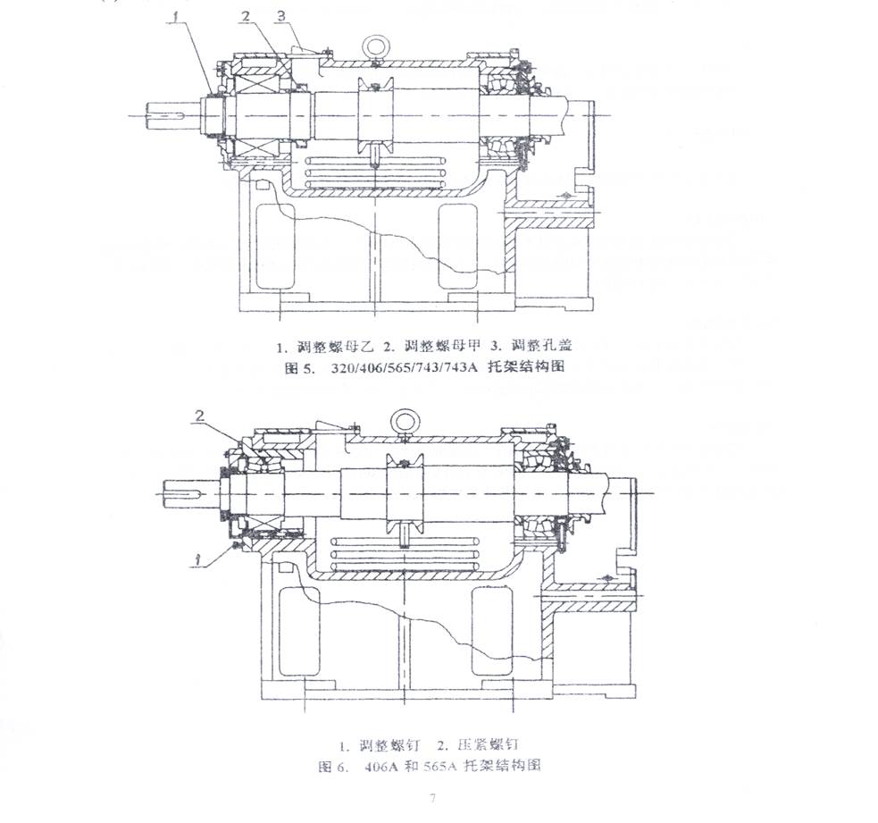
(3) For slurry pumps with the packing-plus-expeller combination seal or the packing seal, turn the shaft by hand in the direction of pump rotation; the shaft should be able to drive the impeller without any rubbing — otherwise the impeller clearance should be adjusted (for mechanically sealed slurry pumps, provided the mechanical seal is correctly installed, the impeller clearance generally needs no further adjustment). Depending on the working pressure, this series of pumps uses different frame types; the two structures shown in Fig. 5 and Fig. 6 are described one by one below, together with their methods of adjusting the impeller clearance.
For the frame shown in Fig. 5, the impeller clearance is adjusted as follows: to adjust the impeller backward, open the adjustment hole cover 3, loosen adjustment nut 2 and tighten adjustment nut 1; once the clearance meets the requirement, tighten adjustment nuts 1 and 2 and refit the adjustment hole cover 3; to adjust in the opposite direction, loosen nut 1 and tighten nut 2.
For the frame shown in Fig. 6, the impeller clearance is adjusted as follows: to adjust the impeller forward, loosen adjustment screw 1 and tighten clamping screw 2 until the clearance meets the requirement; to adjust in the opposite direction, loosen clamping screw 2 and tighten adjustment screw 1 until the required clearance is obtained, then tighten clamping screw 2.
(4) Disconnect the coupling, start the motor and check its direction of rotation; the pump shaft must rotate in the direction of the arrow marked on the casing. Running the pump in reverse with the motor is strictly prohibited; otherwise the impeller will come off and cause an accident.
(5) For direct-coupled drives, the pump shaft and the motor shaft must be precisely aligned to avoid vibration and wear.
(6) Install a removable short pipe or expansion joint in the suction pipe of the pump, of a length sufficient for removing the casing cover and replacing worn parts, so as to facilitate pump maintenance.
(7) For the expeller-plus-packing combination seal, check the leakage at the packing: before start-up, first turn on the shaft seal water; if the leakage is excessive, tighten the packing nuts until the leakage is reduced to a dripping pattern. After the pump is started, if the leakage is not large but the packing heats up, the gland nuts may be loosened slightly; if the packing continues to heat up, stop the pump, let it cool down, adjust the gland nuts and relax the packing so that the leakage increases slightly, then restart the pump; after the packing and the shaft sleeve have run in with each other, adjust the gland nuts again to reduce the leakage.
(8) For mechanical seals, check before the pump is started that the mechanical seal is correctly installed: connect the port of the mechanical seal to the shaft seal water line (for a newly installed shaft seal water line, the welding slag, sediment and other debris remaining in the line should be removed or flushed out clean beforehand), start the shaft seal water pump, open the valve on the shaft seal water line and turn the pump shaft by hand; if dripping occurs, this indicates that dirt is present on the sealing faces — loosen the gland bolts, flush with clean water and then retighten the gland. If no leakage is found, the seal is correctly installed.
Start the shaft seal water pump; the shaft seal water pressure should be more than 0.1 MPa higher than the working pressure of the slurry pump. Wait for five minutes after the shaft seal water has entered the stuffing box chamber before starting the slurry pump.
(9) Before the pump handles slurry, start it on clean water where possible.
4.2 Running
During operation, check the pressure and flow of the shaft seal water at regular intervals. For the expeller-plus-packing combination seal, adjust the tightness of the gland promptly and replace the packing periodically to ensure that a small amount of clean water always passes along the shaft. For mechanically sealed slurry pumps, operation without shaft seal water or with insufficient shaft seal water pressure is not permitted.
Regularly check the condition of the frame, and periodically check the cleanliness and level of the lubricating oil. To prevent bearing overheating, the frame is provided with two cooling circuits, inner and outer, to which cooling water may be added when necessary. For the reserved cooling water connections and the cooling water pressure, refer to Table 1.
4.3 Stopping the pump
Before stopping the pump, let it pump clean water for a while where possible to flush the slurry passing through the pump, then close the pump, its outlet valve and the shaft seal water in sequence. For slurry pumps with mechanical seals, stop the shaft seal water five minutes after stopping the pump.
5. Maintenance
To keep the pump operating safely and economically, pay attention to daily maintenance. Please note the following aspects of maintenance:
5.1 Shaft seal maintenance
Regularly monitor the shaft seal water pressure and flow. For the expeller-plus-packing combination seal, a small amount of clean water must always be kept flowing along the shaft; adjust the tightness of the gland and replace the packing at regular intervals. For mechanical seals, the supply of high-pressure shaft seal water must be ensured. The shaft seal water pressure and flow must comply with the requirements (as described in 2.3).
5.2 Impeller adjustment
To keep the pump running properly, for slurry pumps with the expeller-plus-packing combination seal the axial clearance of the impeller should be adjusted promptly. Generally, for pumps with the expeller-plus-packing seal, adjusting the impeller forward is beneficial to pump performance, while adjusting it backward enhances the shaft sealing effect, so users may adjust according to actual needs. When adjusting the impeller clearance, first stop the pump, then carry out the adjustment following the impeller adjustment method described above.
5.3 Bearing lubrication
Regularly check the condition of the bearings and the lubricating oil in the frame; No. 20, No. 30 or No. 40 machine lubricating oil is generally used. Change the oil after the first 300 hours of operation. After normal operation has been established, if the bearing temperature is below 50°C, an oil change every 3000 operating hours is recommended; if the bearing temperature is above 50°C, an oil change every 2000 operating hours is recommended. Users may determine the oil change interval according to actual conditions.
6. Possible faults and remedies
| Fault | Cause | Remedy |
|---|---|---|
| Pump fails to draw water | Air entering the suction pipe or at the packing Wrong direction of rotation or damaged impeller Suction pipe blocked Pump installed too high above the suction liquid level |
Seal the air leaks Check the direction of rotation; fit a new impeller Clear the blockage Raise the liquid level to satisfy the suction requirement |
| Excessive shaft power | Gland too tight, packing heating up Rubbing inside the pump Bearing damaged Pump flow too high Speed too high, specific gravity too high Motor shaft and pump shaft misaligned or unbalanced |
Loosen the gland bolts Eliminate the rubbing Replace the bearing Adjust the pump operating condition Adjust the speed Align the motor shaft and the pump shaft |
| Bearing overheating | Too much or too little bearing grease Foreign matter in the grease Bearing damaged |
Apply the correct amount of grease Renew the grease Fit a new bearing |
| Short bearing life | Motor shaft and pump shaft misaligned or not parallel; shaft bent Rubbing inside the pump or impeller out of balance Foreign matter in the bearing or improper grease quantity Improper bearing assembly |
Align the motor shaft and the bearing Replace the shaft Eliminate the rubbing; fit a new impeller Replace the bearing or reassemble the bearing |
| Pump vibrates with loud noise | Bearing damaged Impeller out of balance Air entering the suction pipe; blockage Non-uniform flow, pump losing suction Cavitation occurring |
Fit a new bearing Fit a new impeller Eliminate air ingress; clear the blockage Improve the pump feed conditions Eliminate the cavitation |